
- Ssd1963 stm32 driver how to#
- Ssd1963 stm32 driver driver#
- Ssd1963 stm32 driver license#
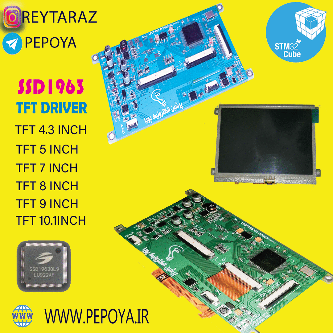
STM32 development board flexible cable input interface pin description.IIC bus clock pin of capacitive touch screen (SPI bus clock pin of resistance touch screen) Touch screen interrupt detection pin(Low level when a touch occurs)Ĭapacitor touch screen reset pin (resistance touch screen chip selection pin) IIC bus data pin of capacitive touch screen (SPI bus write data pin of resistance touch screen) Resistance touch screen SPI bus read data pin (capacitor touch screen not used) Module power supply positive pin (connected to 5V)

LCD tearing effect signal pin (read only)

LCD 16 bit data bus pin (use d0 ~ D7 in 8-bit mode) LCD register / data selection control pin(high level: register, low level: data)
STM32 development board row pin input interface pin description. ①-40pin flexible cable output interface ②④-In line interface of esp32 development board ③-STM32 development board 32pin flexible cable input interface ⑤-STM32 development board 34pin pin input interface 
Input interface of esp32 development board
Ssd1963 stm32 driver driver#
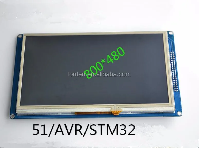
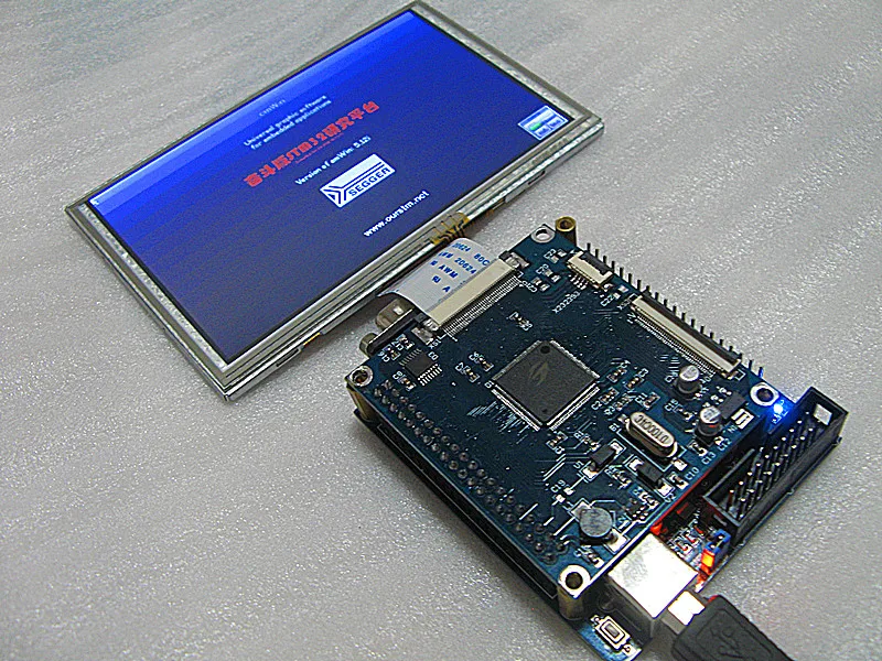
Provide technical support for underlying driver. Military grade process standard, long-term stable work. Provide rich STM32 platform and esp32 platform sample program. Support 8-bit and 16 bit parallel bus transmission, transmission speed block. Support direct connection of RGB display module flexible cable. Support direct insertion of esp32 development board. Support the direct connection of flexible cable and needle of STM32 development board. Support the highest resolution of 800*480. Flip are pretty straight forward, but for mode I have all those options and I'm kind of lost on which should I be using. I still have two things that I didn't get.ġ) Looking at the struct from example board file above, it's missing 3 things. I will do all the recommended tests using a scope and check timings in display datasheet, as suggested. Unless I missed something, all the pins are correctly set, including Register Select which is PD11. PalSetBusMode(&busE, PAL_MODE_ALTERNATE(12)) PalSetBusMode(&busD, PAL_MODE_ALTERNATE(12)) Static const LCD_Parameters DisplayTimings = You will need to change it for your CPU and/or operating system. * This file contains a mix of hardware specific and operating system specific * GDISP Graphic Driver subsystem board interface for the SSD1963 display. * boards/addons/gdisp/board_SSD1963_fsmc.h Ssd1963 stm32 driver license#
* the license was not distributed with this file, you can obtain one at: * This file is subject to the terms of the GFX License. #define GDISP_RAM (*((volatile uint16_t *) 0圆0020000)) /* RS = 1 */Īttached is an image showing what happens. Basically, there is no image on display, only vertical lines in a white backgroud. Anyone could please explain these lines to me? I can see from where 0圆0000000 come from, but what about 0圆0020000?
Ssd1963 stm32 driver how to#
I don't know if the selected mode is wrong and how to change it or fi I have the FMC peripheral initialized properly. I'm trying to get this display working with my STM32F746ZG based nucleo144 board.ĭisplay is 800x480px 7" drived by SSD1963 in 16-bit 8080 parallel mode. H! I've been trying to make this work without success so if anyone could help me I would be very glad.


 0 kommentar(er)
